Stallcup Electrical Education
Write your awesome label here.
Publication Series
2023 Generators, Transformers, and Motors
Stallcup's "Generators, Transformers, and Motors" publication stands as a definitive guide in the realm of electrical engineering, offering comprehensive insights into the design, operation, and maintenance of essential power components. Meticulously curated and updated to reflect the latest advancements and industry standards, this authoritative resource serves as an invaluable tool for engineers, electricians, and students alike.
Covering a wide range of topics including generator types and applications, transformer design and operation, motor characteristics, and maintenance practices, Stallcup's publication provides a deep dive into the fundamental principles and practical considerations necessary for ensuring efficient and reliable electrical power systems. Whether used as a reference for daily operations or as a study guide for professional development, Stallcup's "Generators, Transformers, and Motors" remains essential for those striving to excel in the dynamic field of electrical engineering and technology.
Full Completed Publications
There are many options to choose from in a interactive digital pdf format.
Engaging and Effective Text
Full body text, step-by-step calculations, notes, for example, tips, and so much more.
Interactive Table of Contents
Interactivity at the highest level. Quick access to chapters and topics.
New Graphics
All new 2023 publications have been upgraded with new graphics.
Colored Illustrations
The new graphics have been colored and are visually stunning.
Illustration Overload
Illustrations with step-by-step calculations, NEC and NFPA standard loops, and so much more.
Publications and presentations
Instructors use both to help students retain the pertinent information being presented.
Engaging and effective presentations
New graphics and illustrations developed to capture the students attention and visually stunning.
Interactive presentations
Interactivity at the highest level. Quick access to chapters and topics.
Example Illustrations - Best in the Electrical Industry
Write your awesome label here.
Write your awesome label here.
Write your awesome label here.
Write your awesome label here.
Write your awesome label here.
Write your awesome label here.
2023 Generator Publication
Table of Contents - Extensive Coverage
Magnetism and Electromagnetism
Theory of Magnets
Magnetic Fields
Natural Magnets
Permanent Magnets
Electromagnets
Magnetic Field
Electromagnetics
Electromagnetic Induction
Generator Action
Generator Principles
Basic Operation of Generators
Basic Operation of Direct-Current (DC) Generators
Commutator
Commutator
Armature Reaction
Generated Voltage
The Difference Between a Generator and Motor Typical Synchronous Generator
Generator Exciters
Typical Induction Generator
Types of Engines
Single-Phase Generators
Three-Phase Generators
Components of an AC Generator
Wye-Connected Systems
Delta-Connected Systems
Types of Rotors
Cooling Systems
Regulators
Manual Synchronization of Generators
Automatic Synchronization of Generators
Generators and the National Electrical Code
Location of Generators
Nameplate Markings
Overcurrent Protection for Generators
Ampacity of Conductors From Generators
Protection of Live Parts
Guards for Attendants
Bushings
Generator Terminal Housings
Disconnecting Means Required for Generators
Generators Supplying Multiple Loads
GFCI Protection for Receptacles on 15 kW or Smaller Portable Generators Portable Generators 15 kW or Less
Emergency System Generators
Generator Set
Purpose and Scope of Emergency Generators
Sizing Generators
Sizing Generators
Transfer Switch and Equipment
Wiring Identification
Wiring Systems
Feeder Wiring Protection
Feeder Circuit Equipment
Source Control Wiring
Coordination
Grounding
Legally Required and Optional Standby Generators
Legally Required Standby Systems
Purpose of Legally Required Standby System
Sizing Generators - Legally Required Standby Systems
Transfer Switches and Equipment - Legally Required Standby Systems Wiring Legally Required Standby Systems
Overcurrent Protection Devices - Accessibility
Grounding - Legally Required Standby Systems
Optional Standby Systems
Sizing Optional Standby Generators
Transfer Switches and Equipment - Optional Standby Systems
Wiring Optional Standby Systems
Portable Generator Grounding
Grounding of Permanently Installed Generators
Sign for Power Inlet
Generators Supplying Essential Loads for Hospitals
Life Safety Branch
Critical Branch
Equipment Branch
Transfer Switches
Optional Loads
Wiring Requirements Separation From Other Circuits
Isolation and Protection
Capacity of Systems
Isolation and Protection
Capacity of Systems
Sources of Power
Generator Grounding for 480 V to 1000 V systems
Generator Grounding of 1000 Volts or More
Separately Derived Systems
Generator Grounding of 1000 Volts or More
Separately Derived Systems
Permanently Installed Generators
Methods of Grounding
Solidly Grounded Generators
Resistance-Grounded Generators
Reactance-Grounded Generators
Resistance-Grounded Generators
Reactance-Grounded Generators
Portable Generators
Transfer Switch is not Provided
2023 Transformer Publication
Table of Contents - Extensive Coverage
Transformer Theory
Transformer principles
Windings
Single-phase output
Wye-connected secondaries
Delta-connected transformers
Delta-connected transformers
Balancing loads on transformer windings
Derating for high altitude
Derating for high altitude
Installing Transformers
Marking
Guarding
Ventilation of Transformers
Accessibility of Transformers
Disconnecting Means
Dry-Type Transformers Installed Indoors
Dry-Type Transformers Installed Outdoors
Less-Flammable Liquid-Insulated Transformers
Non-Flammable Fluid-Insulated Transformers
Askarel-Insulated Transformers Installed Indoors
Oil-Insulated Transformers Installed Indoors
Oil-Insulated Transformers Installed Outdoors
Modification of Transformers
Dry-Type Transformers Installed Outdoors
Less-Flammable Liquid-Insulated Transformers
Non-Flammable Fluid-Insulated Transformers
Askarel-Insulated Transformers Installed Indoors
Oil-Insulated Transformers Installed Indoors
Oil-Insulated Transformers Installed Outdoors
Modification of Transformers
Transformer Vaults
Walls, Roofs, and Floors
Doorways
Doorways
Ventilation Openings
Drainage
Drainage
Water Pipes and Accessories
Storage in Vaults
Storage in Vaults
Sizing Transformers and Connections
Sizing Wye-Connected Secondaries
Sizing Closed Delta-Connected Secondaries
Sizing Open Delta-Connected Secondaries
Sizing Autotransformers
Sizing Connections From the Secondary of Transformers
Supervised Industrial Installations - Feeder and Branch-Circuit Conductors
Protecting Transformers
Calculating Primary and Secondary Current
Finding Amperage
Finding Amperage
Calculating Fault Currents
Overcurrent Protection
Protecting Transformers
Overcurrent Protection - Primary Only Over 1000 Volts
Overcurrent Protection - Primary and Secondary Over 1000 Volts
Overcurrent Protection - Supervised Locations
Overcurrent Protection - Non-Supervised Locations
Overcurrent Protection - Primary Only 1000 Volts or Less
Overcurrent Protection - Primary 9 Amps or More
Overcurrent Protection - Primary 2 Amps or More But Less Then 9 Amps
Overcurrent Protection - Primary Less Than 2 Amps
Overcurrent Protection - Primary and Secondary 1000 Volts or Less
Calculating Overcurrent Protection Devices for Autotransformers Grounding Autotransformers
Secondary Ties
Tie Circuits
Radial Supply Systems
Loop Supply Systems
Bus-Tie Loops
Loop Supply Systems
Bus-Tie Loops
Bus-Tie Conductors
Bus-Tie Protection
Bus-Tie Protection
Network Power Systems
Windings and Components
Testing Windings
Testing for Polarity
Polarity Connections and Identifying Terminals
Testing Voltage of Windings
Testing Voltage of Windings
Identifying and Connecting Windings
Separately Derived AC Systems
Troubleshooting Transformer Windings
Separately Derived AC Systems
Troubleshooting Transformer Windings
2023 Motor Publication
Table of Contents - Extensive Coverage
Motor Theory
Regular Magnets
Electromagnets
Basic Induction Motors
Field Poles
Designs of Motors
Motor Facts
Operating 230 V Motors on 208 V Supply Circuit
Measuring Operating Amps
Measuring Operating Amps
Measuring Operating Voltage
Types of Motors
Single-Phase Motors
Split-Phase Motors
Capacitor-Start Motors
Capacitor-Start Motors
Capacitor Start-and-Run Motors
Permanent Split-Capacitor Motors
Shaded-Pole Motors
Permanent Split-Capacitor Motors
Shaded-Pole Motors
Universal Motors
Repulsion Motors
Three-Phase Motors Squirrel-Cage Induction Motors
Synchronous Motors
Synchronous Motors
Wound Rotor Motors
NEMA Type Enclosures
Design Letters and Code Letters
Types of Motors
Calculating Torque
Code Letters
Starting Methods
Types of Starting Methods
Adjustable Frequency Drives
Eddy-Current Drives
Purpose of Clutch
Adjustable Frequency Drives
Eddy-Current Drives
Purpose of Clutch
Wye-Delta Starting Methods
Part-Winding Starting Methods Overcurrent Protection
Part-Winding Starting Methods Overcurrent Protection
Overcurrent Protection for Individual Motors
Short Circuit, Ground Fault, and Overload Protection
Sizing and Selecting Overcurrent Protection Devices
Obtaining FLC Ratings
Sizing and Selecting Overcurrent Protection Devices
Obtaining FLC Ratings
FLC for Unlisted Motors
FLC Ratings Using Rule-of-Thumb Method
Sizing Maximum Overcurrent Protection Device
Sizing Overcurrent Protection Devices to Allow Motors to Start and Run
Motors Connected to Individual Branch Circuits
Motors Connected to Individual Branch Circuits
Automatic Restarting
Sizing an Overcurrent Protection Device for Two or More Motors Conductors With Ampacities Greater than Motor’s FLC
Future Additions
OLP for Motors
Overload Protection for Individual Motors
Minimum Size Overload Protection
Service Factor
Service Factor
Temperature Rise
Maximum Size Overload Protection
Single-Phasing
Single-Phasing
Shunting Overloads During Starting Period
Sizing Controllers
Sizing the Disconnecting Means to Disconnect Both the Controller and Motor
Location of the Disconnecting Means for theController and Motor
Location of the Disconnecting Means for theController and Motor
Motor Feeder and Branch Circuit Conductors
Sizing Conductors for Single Motors
Sizing Conductors for Single-Phase Motors
Sizing Conductors for Three-Phase Motors
Direct-Current Motor-Rectifier Supplied
Sizing Conductors for Multispeed Motors
Sizing Conductors for Wye-Start and Delta-Run Motors
Sizing Conductors for Part-Winding Motors
Sizing Conductors for Part-Winding Motors
Sizing Conductors for Duty Cycle Motors
Sizing Conductors for Adjustable Speed Drive Systems
Wound Rotor Secondary
Wound Rotor Secondary
Sizing Conductors for Several Motors
Sizing Motors on a Feeder
Sizing Conductors for Motors and Other Loads
Feeder Demand Factors
DC Motors
Sizing Conductors for Capacitors
Motor Control Centers
Adjustable Speed Drive Systems
Phase Converters
Fire Pumps
Control Circuit Conductors and Components
Types of Control Circuits
Conductor Protection
Protection of Conductor from Physical Damage
Electrical Arrangement of Control Circuits
Disconnection of Control Circuit Conductors and Power Class 1 Circuits
Class 2 and 3 Circuits
Control Circuits in Raceways, Cables, and Enclosures
When to Derate the Ampacity
When to Derate the Ampacity
Motor Control Center Transformer
Connecting Controls for Operation
Magnetic Starters
Two-Wire Control Systems
Three-Wire Control Systems
Control Devices
Troubleshooting Motor Windings and Components
Troubleshooting Split-Phase Motors
Single-Phase, Squirrel-Cage Induction Motors
Single-Phase, Shaded-Pole Motors
Universal Motors
Single-Phase Repulsion Motors
Troubleshooting Three-Phase Induction Motors
Testing and Finding the Leads of Delta Motors
Troubleshooting Wound-Rotor Motors
Troubleshooting Synchronous Motors
Troubleshooting DC Motors
Troubleshooting Control Circuits
Testing Control Devices
Troubleshooting Variable Frequency Drives (VFD)
Troubleshooting Eddy-Current Drives
Troubleshooting Eddy-Current Drives
Troubleshooting the Windings of a Wye Motor for Grounds Troubleshooting the Windings of a Delta Motor for Grounds Troubleshooting Solid State Circuit Boards
Compressor Motors
Nameplate Listing
Marking on Hermetic Refrigerant Motor-Compressors and Equipment Markings on Controllers
Ampacity and Rating
Highest Rated (Largest) Motor
Single Machine
Disconnecting Means
Rating and Interrupting Capacity
Cord-Connected Equipment
Location
Application and Selection
Branch Circuit Conductors
Single Motor-Compressors
Two or More Motor Compressors
Combination Loads
Controllers for Motor-Compressors
Motor-Compressor and Branch-Circuit Overload Protection
Overload Relays
Room Air Conditioners
Troubleshooting a Compressor Motor
Other Publications of Interest
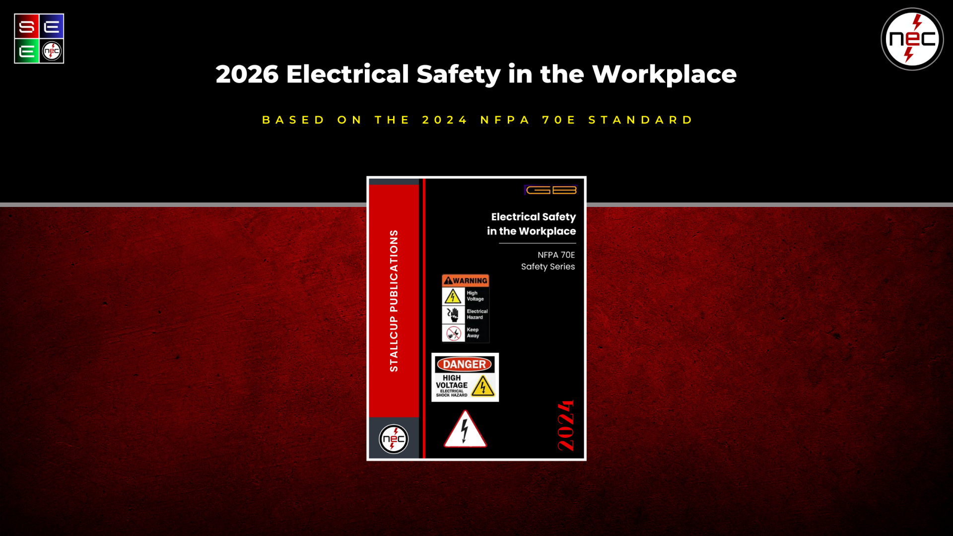
NFPA 70E Electrical Safety in the Workplace (Coming Soon)

